
Slew drives
Worm-gear slew drives with a self-locking output
A slew drive puts a slewing ring, a worm shaft, a sealed housing and a motor flange into one unit. It removes the gearbox, the pinion guard and the alignment work, and the worm ratio holds the load without a brake.
Tell us the load and the rotation. We come back with a size and a price within one working day.
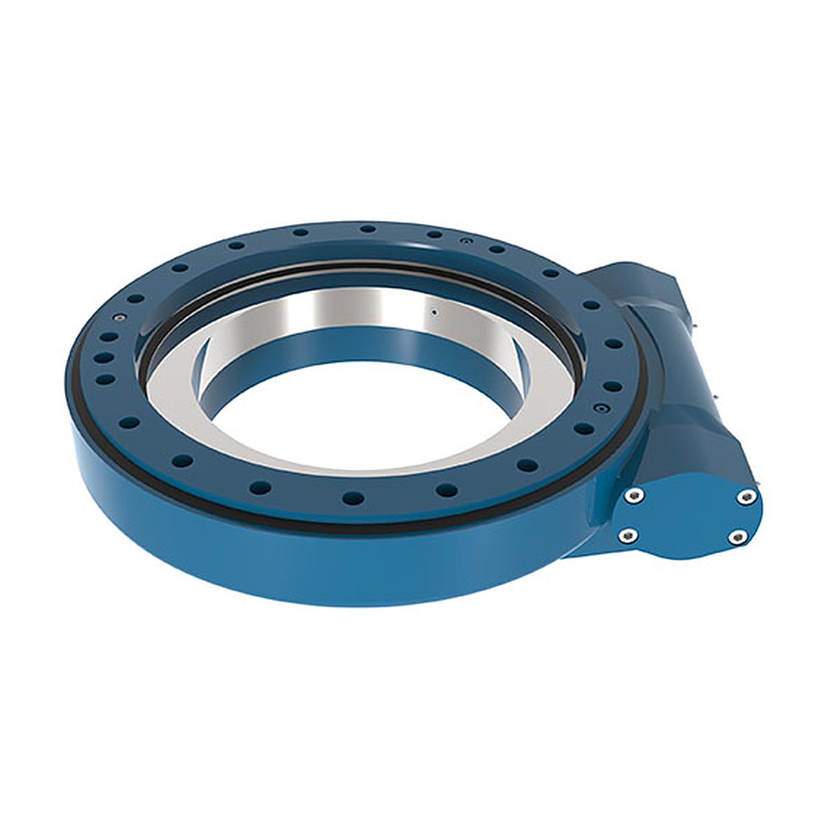
SE series worm slew drive — the ring, the worm and the housing are matched and run in as one unit.
- Housing in ductile iron, sealed grease chamber
- Self-locking ratio for holding load
- Motor flange and output shaft to your drawing
Series
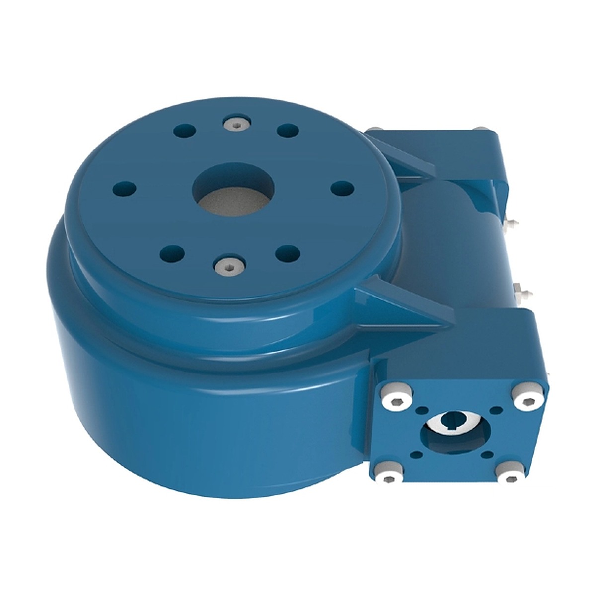
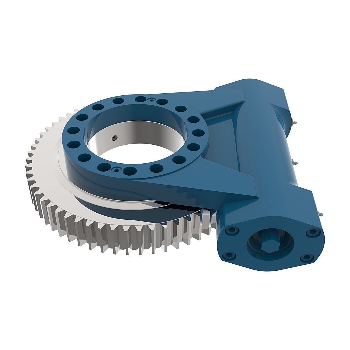
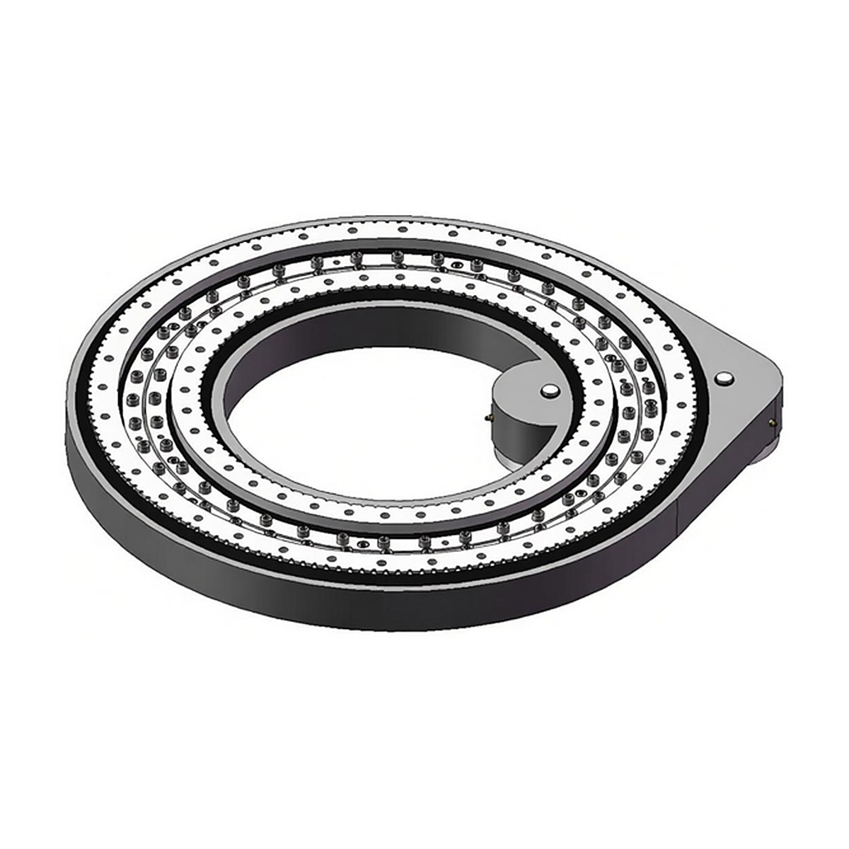
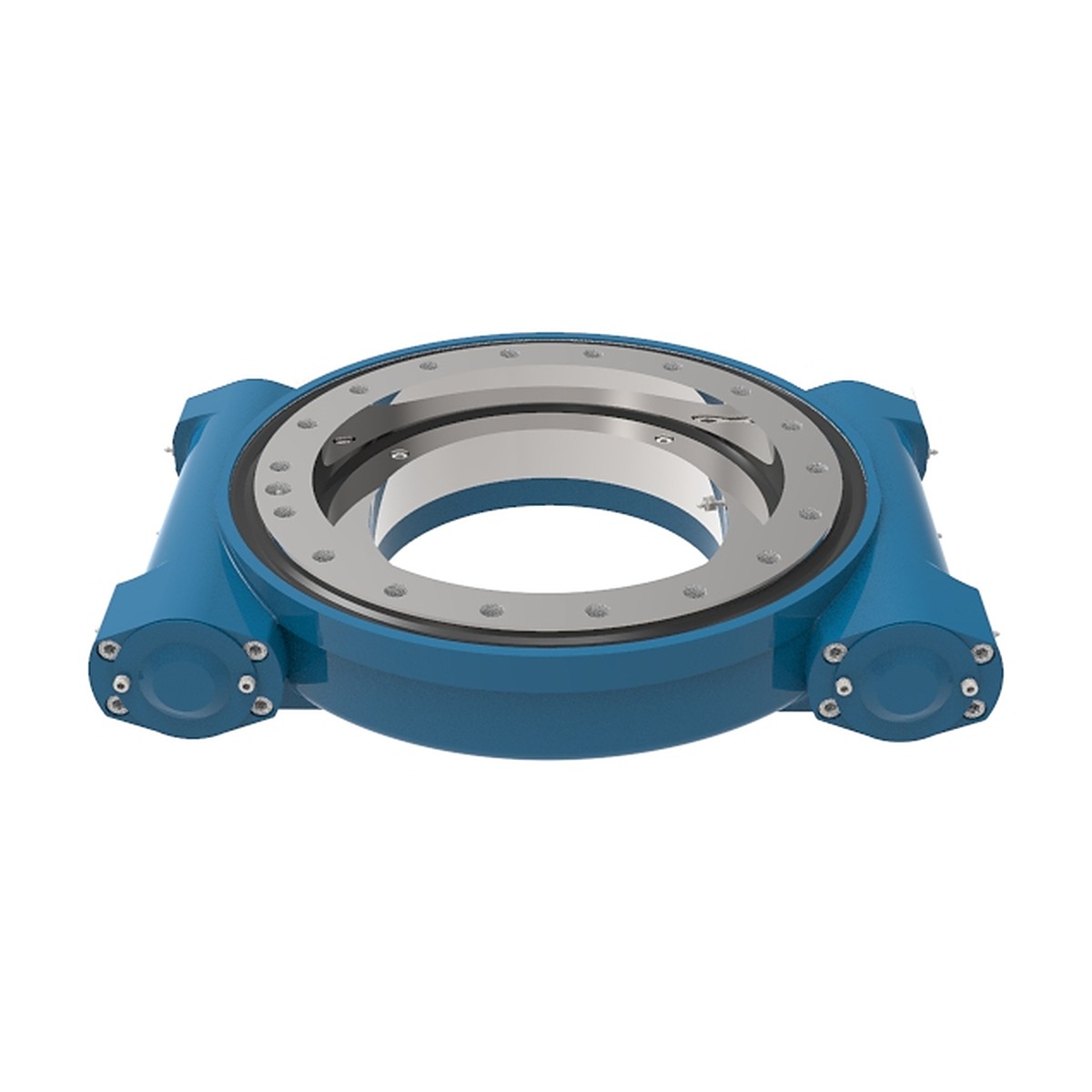
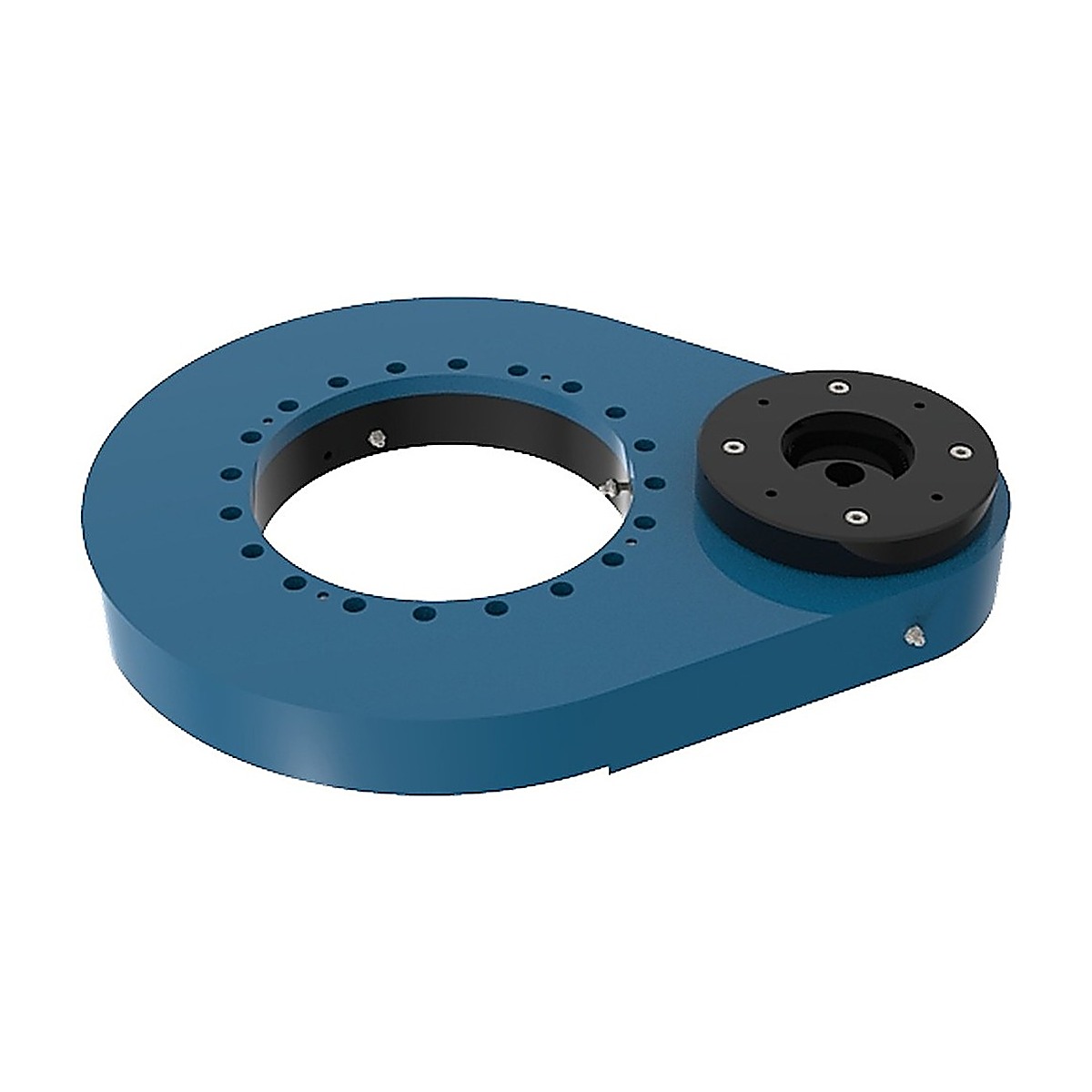
Six drive configurations
Motor interface
Where most projects go wrong
A slew drive is only as good as the joint between its input shaft and your motor. We machine the flange and coupling to the motor drawing you send, so the assembly arrives aligned instead of being reworked on site.
- DC gear motor with encoder
- AC induction motor with brake
- Stepper and servo motor
- Hydraulic motor
- Planetary gearbox input
Solar tracker drives
Tracker drives run outdoors for 25 years, move a few degrees at a time, and must hold position in storm wind without drawing power. That sets three requirements we quote against:
- Holding torque above the wind back-torque at the selected ratio
- Sealing and breathing that survive thermal cycling — condensation kills bearings in the field, not rain
- A repeatable mounting interface so a drive can be swapped without re-shimming
Slew drive guide
A slew drive removes the gearbox, the pinion guard and the alignment work from a rotating machine. This guide covers the configurations, the torque and ratio decisions, and how the worm stage holds a load without a brake.
What is a slew drive?
A slew drive is a slewing bearing with the drive built into it. A worm shaft runs in a sealed housing, meshes with gear teeth cut on the bearing’s outer ring, and the whole assembly bolts to the machine through a flange. Motor in, rotation out — no separate gearbox, no pinion guard, no alignment work on site.
The single-start worm gives a large reduction in one stage, so a compact housing produces a slow, high-torque output. Because the worm thread slides against the wheel teeth rather than rolling over them, the stage is normally self-locking: with the motor de-energised the load stays where it is, and no brake is needed to hold position.
The bearing inside does the load carrying. Axial load, radial load and tilting moment pass through the ring and its raceway exactly as they would in a stand-alone slewing ring; the worm stage only adds torque. That division of labour is why a slew drive can be small in section yet move a heavy structure slowly and hold it still.
Types of slew drives
Six configurations cover the mounting positions and duty levels found in most machines.
- SE enclosed — the workhorse. Horizontal flange, worm entering from the side, sealed housing rated for outdoor duty. Used on trackers, cranes and industrial turntables.
- VE vertical — vertical output axis, for structures that rotate about a vertical centre line with the drive mounted underneath or beside.
- S compact — small housing, single-axis motion, lowest cost. For turntables and light platforms where a full-size drive is more than the load requires.
- WE horizontal — horizontal output axis, side-mounted, for rotation in a vertical plane such as a tilting platform or a hinged frame.
- WED double worm — two worm stages in series for a higher total ratio and higher output torque from the same envelope.
- SDE compact low-backlash — reduced backlash for positioning work where the load must stop within a tight angular band.
Spur gear drives are a separate family, not a variant: they use a parallel-shaft pinion stage instead of a worm, which raises efficiency and speed but gives up self-locking.
Features of slew drives
- Self-locking output — the worm lead angle is below the friction angle, so the load cannot back-drive the motor and no holding brake is required for static load.
- Large reduction in one stage — a compact housing produces the slow output speed a tracker, crane or turntable needs, without a second gearbox.
- Bearing and drive in one part — the ring carries axial, radial and moment load while the worm carries torque, so the machine needs one mounting face instead of two.
- Sealed housing — IP65 as standard on the enclosed series, with the seal and grease chosen for the temperature range you state.
- Motor interface options — flange and shaft to suit DC, AC, servo or hydraulic motors, with the pilot diameter and bolt circle matched to your motor rather than adapted on site.
- Holding torque without a brake — the self-locking stage holds rated load in position with the motor off, which simplifies the control system and removes a wear item.
- Compact axial height — the worm sits beside the ring rather than above it, keeping the stack short in tight envelopes.
- Greased for life — sealed at assembly for the standard duty cycle, with a re-lubrication option where the duty is heavy.
Applications of slew drives
- Solar trackers — single-axis trackers rotate the module row once a day through a few degrees per hour. Slow motion, high wind moment, and a drive that must hold position without power.
- Cranes and lifting equipment — jib cranes, loader cranes and slewing attachments, where the self-locking stage holds a suspended load.
- Aerial work platforms — boom and basket rotation on scissor and boom lifts.
- Industrial turntables — assembly stations, welding positioners and pallet changers rotating under load.
- Robotics and automation — seventh-axis positioners and rotary index tables, often on the low-backlash series.
- Construction and earthmoving — attachments and rotating grapples on compact machines.
- Agriculture — irrigation pivots, rotating feeders and implement rotation.
- Mobile and vehicle-mounted equipment — satellite and radar mounts, camera platforms, rotating beacons and work lights.
The common thread is slow rotation against a large moment in an outdoor environment, with no compressed air and often no room for a separate brake.
Slew drives for sale
Each series is quoted by output torque and ratio rather than by a single model number, because the same housing accepts different worm stages and different motor flanges. Tell us the torque the load needs and the speed it has to turn, and the configuration follows.
Price depends on ring diameter, series, ratio, whether the housing is sealed to IP65, the motor flange and shaft detail, backlash grade on the SDE series, and quantity. A standard enclosed drive in volume is a different proposition from a single low-backlash unit with a custom flange.
Minimum order. One piece for a prototype or a replacement.
Lead time. Stated in the quotation, split between the standard housing and any custom flange or shaft work, so you can see which part of the schedule is fixed and which is not.
Send the load, the required output speed, the motor you intend to fit, and the mounting orientation. If a drive is replacing an existing unit, send the nameplate and the flange drawing.
Slew drive buying guide
Sizing a slew drive is two independent calculations that are often confused: the torque needed to turn the load, and the torque needed to hold it. Both have to be covered.
- Output torque. The torque required to rotate the load, including friction, wind load on a tracker, off-centre mass and acceleration if the motion is not continuous. Add a margin for the starting torque of a loaded, settled structure.
- Holding torque. The torque the self-locking stage must resist with the motor off. On a tracker this is the wind moment; on a crane it is the suspended load. Compare it with the drive’s holding rating, not its output rating.
- Ratio. Set by the output speed you need and the motor speed you have. A higher ratio gives more torque and slower motion, and moves the self-locking margin further into the safe zone.
- Output speed. Degrees per second or revolutions per hour. Trackers are usually specified in degrees per minute; turntables in revolutions per minute. State which you mean.
- Duty cycle. Continuous rotation and occasional indexing load the worm differently. A drive that rotates continuously runs warmer and needs a different grease.
- Backlash. Standard backlash is fine for a tracker or a crane. Positioning equipment needs the low-backlash series, and the number has to be stated in degrees at the output, not at the motor.
- Motor interface. Flange size, pilot diameter, bolt circle, shaft diameter and keyway, plus whether the motor has a brake or an encoder.
- Environment and mounting. IP rating, temperature range, and whether the output axis is horizontal or vertical — the mounting orientation changes the lubrication and, on some series, the permissible load.
Working principle of a slew drive
The drive stage is a worm and wheel. The worm is a screw-like shaft with a helical thread; the wheel is the bearing’s outer ring with gear teeth cut on its circumference. Because the worm has a single start, one full turn of the worm advances the wheel by a single tooth — which is where the large reduction comes from.
The contact between worm thread and wheel tooth is sliding, not rolling. That has two consequences. First, efficiency is lower than a spur stage — a meaningful share of the input energy leaves as heat rather than as torque. Second, and more usefully, sliding contact with a shallow lead angle produces self-locking: the friction between thread and tooth is greater than the force trying to push the wheel backwards, so the load cannot drive the worm.
The self-locking condition depends on the lead angle being below the friction angle for the material pair and the lubricant. This is why a slew drive should not be treated as self-locking by assumption when the load is vibratory or the ratio is low — a brake is still the right answer for some duty cycles, and we will say so when the numbers point that way.
The bearing underneath behaves as any slewing ring does: the worm’s tangential force adds to the load case at the pitch circle, and axial, radial and moment load pass through the raceway. Torque never bypasses the bearing.
How does a slew drive work?
From the outside the unit has one input and one output. The sequence through it is short.
- Motor to worm. The motor couples to the worm shaft through a flange and either a direct shaft connection or a coupling. Alignment is fixed by the housing, which is the point of buying the drive as one assembly.
- Worm to wheel. The worm thread drives the gear teeth on the ring. Reduction happens here, in one stage, and the output turns at the ratio-divided motor speed.
- Wheel to structure. The ring is bolted to the rotating part of the machine; the housing is bolted to the fixed frame. The ring rotates, the housing stays still.
- Load through the raceway. Whatever the structure weighs and whatever the wind or the payload adds passes through the bearing raceway, not through the worm. This is why the worm can be small relative to the load it appears to move.
- Holding position. With the motor off, the self-locking stage resists the load. On a tracker this is what keeps the array in place overnight and in gust conditions.
- Maintenance. Check the seal and the mounting bolts at the interval stated for the series, and confirm the grease condition where a re-lubrication nipple is fitted. Water ingress at the seal is the most common cause of an early failure.
Customize your slew drive
The housing and the bearing are fixed by the series; almost everything bolted to them can be changed.
- Ratio — the worm stage is selected to hit your output speed and torque, within the range the series allows.
- Motor flange and shaft — pilot diameter, bolt circle, shaft diameter and keyway cut to your motor drawing rather than adapted with a plate.
- Output flange — bolt pattern, pilot, tapped or through holes, to match the rotating structure.
- Backlash grade — standard or reduced, stated in degrees at the output.
- Sealing and IP rating — IP65 as standard, with higher protection or a different seal material where washdown or temperature demands it.
- Paint and corrosion protection — coating system matched to coastal or chemical exposure, with the colour to your specification.
- Options — encoder mounting, brake, limit switch bracket, second shaft end, low-temperature grease, food-grade lubricant.
- Documentation — torque test record, backlash measurement, ratio verification and material certificates.
Slew drive packaging & shipping
A slew drive arrives with a sealed housing, a greased raceway and a machined flange face. Packing has to protect all three.
- Flange face protection — the machined mounting face is covered so it cannot be bruised in transit, since a burr there becomes a mounting error on site.
- Seal protection — the unit is packed so the output seal is not loaded by the weight of the drive, and the shaft or flange is supported rather than hanging.
- Moisture control — VCI film and desiccant inside a sealed bag, because a sealed housing still draws condensation through temperature cycling in a container.
- Crate — plywood case or wooden crate with the drive blocked in all three axes, and the crate sized for pallet handling rather than manual lifting.
- Documents — packing list, inspection record, and certificate of origin in an outside pocket.
- Terms — EXW, FOB or CIF; sea LCL or FCL for volume, air for schedule-critical replacements. Insurance on request.
If several drives ship together, they are packed so that flanges do not touch and the units can be lifted out one at a time without unpacking the whole crate.
Slew drive manufacturer
A slew drive is a bearing and a gearbox sharing one housing, and that sharing is where quality is won or lost. The worm must sit at the right centre distance from the ring, the bearing clearance must be set before the housing is closed, and the seal must survive the same environment as the raceway.
The production route runs: ring and housing machining → gear cutting on the ring → raceway hardening and grinding → worm shaft grinding → housing assembly with bearing and seal → backlash and torque check → run-in → sealing test → painting → packing.
Two checks matter more than the rest. Backlash is measured at the output, in degrees, on the assembled unit — not inferred from the tooth thickness. And the sealing test is done on the closed housing, because a drive that passes a bench test and leaks in service is a warranty claim, not a specification.
Buying from the maker means the bearing clearance, the gear cut and the housing bore are held by one tolerance chain. When a drive is assembled from parts bought separately, that chain has three owners and the backlash you measure is the sum of their errors.
FAQ of slew drives
Is a slew drive really self-locking?
Normally yes, because the single-start worm’s lead angle is below the friction angle. It should not be assumed for every case: low ratio, vibration, or a lubricant that reduces friction can let the load creep. Where the numbers are marginal we recommend a brake rather than relying on the worm.
What efficiency should I expect?
A worm stage is a sliding contact, so efficiency is well below a spur stage — meaningfully more input energy leaves as heat, and that heat has to be considered in continuous duty. The exact figure depends on ratio, lead angle and lubricant, and is stated with the quotation for the configuration you choose.
Can I fit my own motor?
Yes. Send the motor drawing — flange size, pilot diameter, bolt circle, shaft diameter and keyway. The housing is machined to that interface instead of being adapted with a plate, which keeps the coupling alignment inside the housing.
What IP rating is standard?
IP65 on the enclosed series, which covers rain, spray and dust. Higher protection or a different seal material is available for washdown and for temperature extremes.
How is backlash specified?
In degrees at the output, on the assembled unit. Specifying it at the motor is a common mistake, because the ratio multiplies the error by the same factor it multiplies the torque.
Does mounting orientation matter?
Yes. Horizontal and vertical output axes load the lubrication and, on some series, the permissible load differently. Tell us the orientation and the drive is configured for it.
What is the difference between a slew drive and a spur gear drive?
The reduction stage. A slew drive uses a self-locking worm; a spur gear drive uses a parallel-shaft pinion, which is more efficient and faster but needs a brake to hold position.
Send the motor drawing with the drive enquiry
Flange, shaft, key and pilot dimensions are enough to confirm the interface. No motor chosen yet? Tell us the torque and speed you need.