
Spur gear drives
Spur gear slew drives for higher torque and speed
Where a worm drive is too slow or not efficient enough, a spur gear stage takes over. Spur drives are not self-locking, so they are paired with a brake and an encoder — and they deliver far more output torque per unit of housing volume.
Tell us the load and the rotation. We come back with a size and a price within one working day.
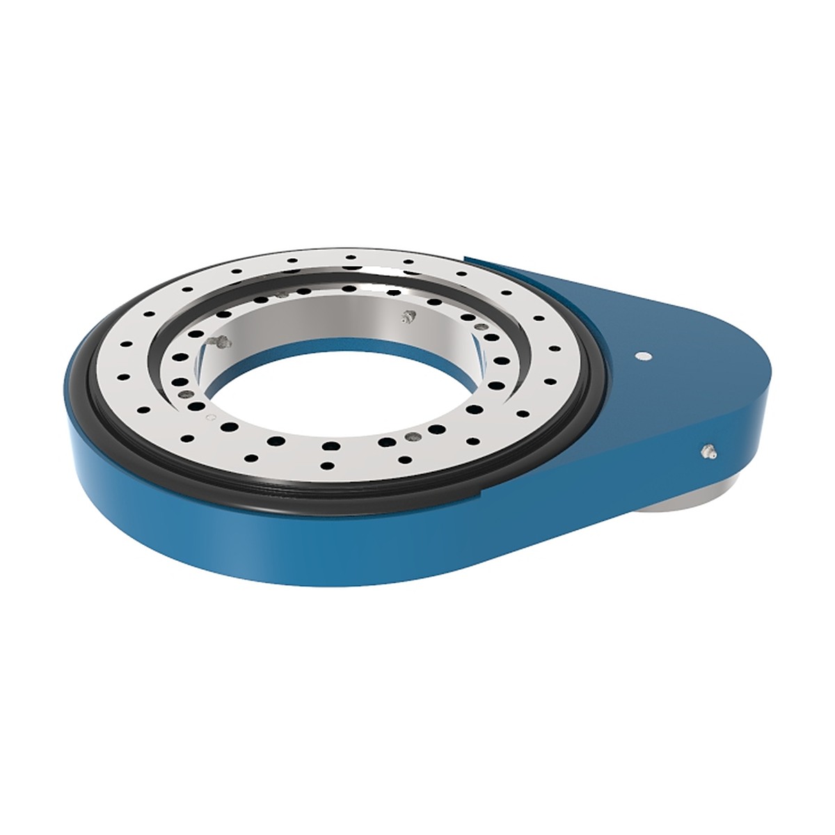
SP-M vertical slew drive — spur gear stage for high torque in a short axial height.
- Case-hardened pinion and gear wheel
- Ratios from 40:1 upwards
- Vertical or horizontal mounting
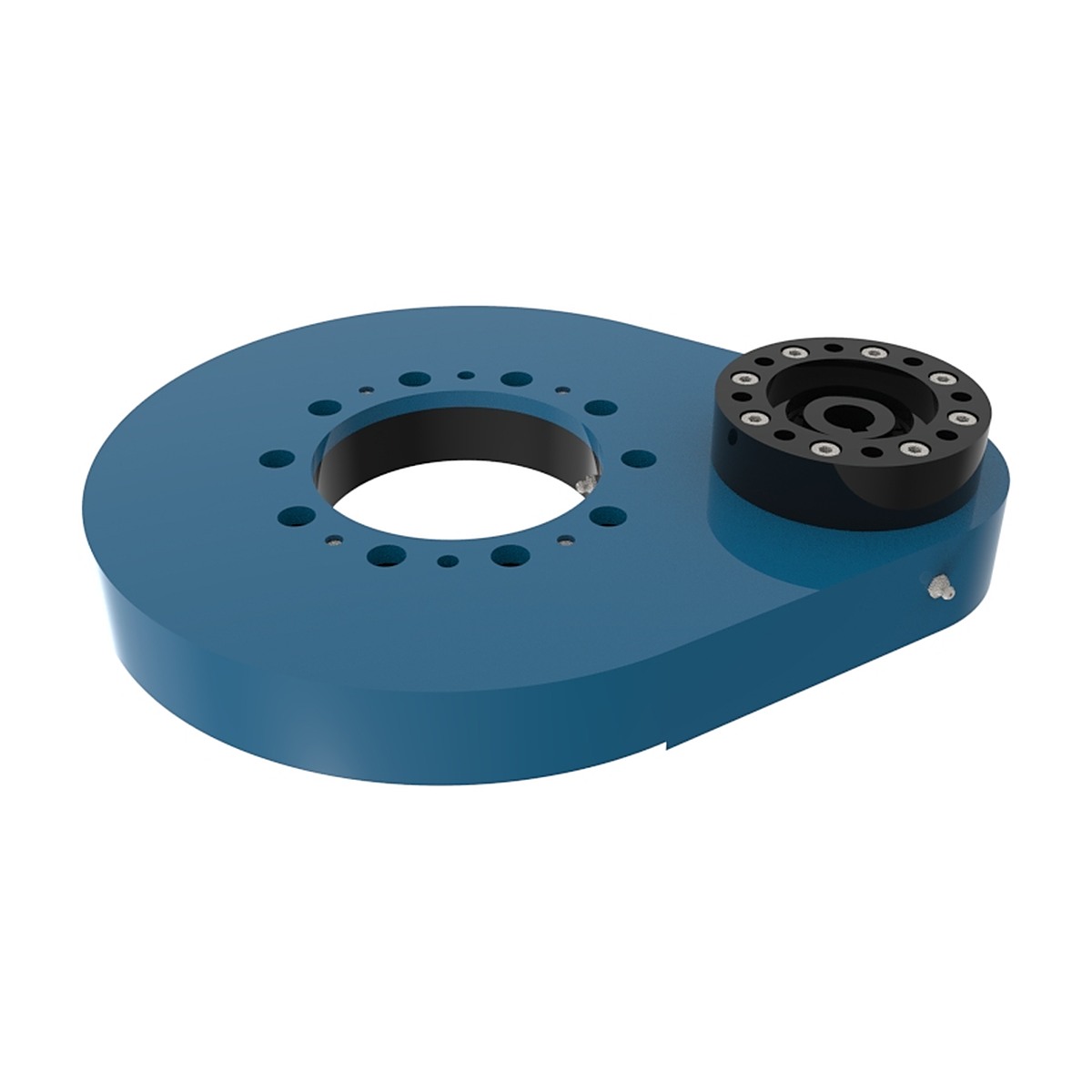
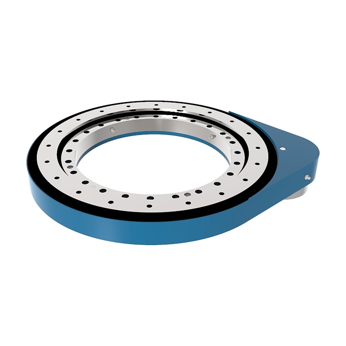
Three series
Spur drive or worm drive?
| Worm gear drive | Spur gear drive | |
|---|---|---|
| Efficiency | Around 40%, self-locking | Higher efficiency, needs a brake |
| Output speed | Low, precise | Higher |
| Torque density | Moderate | High |
| Backlash | Low, held when power is off | Requires brake to hold |
| Best for | Solar trackers, slow positioning | Heavy turntables, machine rotation |
Spur gear drive guide
Where a worm drive trades efficiency for self-locking, a spur stage trades self-locking for speed and efficiency. This guide covers when that trade is the right one, and how to size the brake that comes with it.
What is a spur gear drive?
A spur gear slew drive is a slewing bearing whose outer ring is driven by a spur pinion on a parallel shaft, usually through one or two reduction stages. It does the same job as a worm drive — slow, high-torque rotation of a large structure — but the reduction happens through rolling tooth contact instead of sliding contact.
That single difference changes the character of the unit. A spur stage is efficient, so less input energy becomes heat and more becomes torque. It can run faster without overheating. And it is not self-locking: with the motor de-energised the load can back-drive the pinion, so a brake is part of the design rather than an option.
In practice the family is chosen by what the machine does. A tracker that must hold position overnight without power wants a worm. A machine tool table, a positioner or a radar axis that has to move quickly and stop precisely wants a spur stage with a brake and, usually, an encoder.
Types of spur gear drives
Three duty levels cover the range, and the ring and pinion can also be supplied as separate geared components where the machine builder wants to design its own housing.
- SP-I light duty — compact pinion stage for smaller turntables, display equipment and light positioners where speed matters more than torque.
- SP-M medium duty — the general-purpose series: machine tool tables, welding positioners, indexing stations and mid-size rotary equipment.
- SP-H heavy duty — for large turntables, radar and antenna axes, and heavy positioning work where the moment is high and the motion must still be quick.
- Geared ring and pinion sets — the ring with external or internal teeth plus a matched pinion, supplied without a housing for builders who integrate their own drive train.
- Two-stage configurations — where the required ratio is beyond a single pinion pair, a second reduction stage is added, which is how a spur family reaches worm-like ratios while keeping rolling contact.
Gear teeth can be supplied hardened and ground for quiet running and long life, or soft-cut where the duty is light and the budget is tight.
Features of spur gear drives
- High efficiency — rolling contact between involute teeth loses far less energy to friction than a sliding worm mesh, so more of the motor’s output reaches the load and less heat has to be dissipated.
- Higher output speed — the same motor turns the structure faster, or a smaller motor turns it at the same speed.
- Brake-based holding — the stage is back-drivable by design, so a spring-applied brake holds position when power is removed. This is a feature, not a limitation: it allows the drive to be back-driven deliberately during maintenance or manual positioning.
- Low thermal load in continuous duty — continuous rotation does not build heat the way a worm stage does, which suits indexing tables and production machinery.
- Precise positioning — with hardened and ground teeth plus an encoder, the axis can be positioned within a tight angular band, which is what machine tool and radar work requires.
- Matched pinion — the pinion is cut and, where required, ground as a pair with the ring, so backlash and tooth contact pattern are set at assembly rather than adjusted on site.
- Serviceable — pinion and ring wear can be inspected without dismantling the bearing, and the pinion can be replaced on its own in most configurations.
Applications of spur gear drives
- Machine tools — rotary tables, indexing heads and trunnion axes, where repeatability and stiffness decide the part quality.
- Welding and assembly positioners — continuous or indexing rotation of a fixture under load, often with a strict cycle time.
- Radar and antenna pedestals — azimuth axes that must slew quickly and hold a heading precisely.
- Stage and studio equipment — revolving stages, camera cranes and rigging turntables, where quiet running matters as much as torque.
- Heavy turntables — vehicle turntables, transfer tables and large rotating platforms where the drive must move the load at a usable speed.
- Packaging and filling machinery — rotary carousels running continuously, where efficiency and heat are the deciding factors.
- Test rigs — positioners that must sweep through angles under load with controlled speed, sometimes back-driven by the test article.
- Material handling — rotating grippers and turnover stations on automated lines.
The pattern is consistent: motion that has to be quick, repeated and precise, in a machine that already has a brake and a controller.
Spur gear drives for sale
The series sets the envelope; the ratio, pinion and motor interface are configured per order. Because a spur stage is not self-locking, the brake is quoted with the drive rather than left to the customer to source separately — a drive and a brake sized independently is how axes creep.
Price depends on ring diameter, series, number of reduction stages, tooth hardening and grinding, backlash grade, brake torque, encoder provision and quantity.
Minimum order. One piece for a prototype or a replacement axis.
Lead time. Given in the quotation, separated into standard machining and any custom pinion, flange or brake work.
To quote accurately, send: the torque required at the output, the output speed, the tilting moment and axial load on the ring, the motor and brake you intend to use, and the mounting orientation. If the axis must hold position within a stated number of arc-minutes, say so — that number sets the backlash grade and the grinding route.
Spur gear drive buying guide
The first decision is not a size, it is the family. The table below is the honest comparison.
| Decision | Worm slew drive | Spur gear drive |
|---|---|---|
| Holding position with power off | Self-locking, no brake needed | Back-drivable, brake required |
| Efficiency | Lower — sliding contact, heat in continuous duty | Higher — rolling contact, low heat |
| Output speed | Slow, high ratio in one stage | Faster, ratio built from one or two stages |
| Back-driving | Prevented by the worm | Possible, useful for manual positioning |
| Best fit | Trackers, cranes, unattended holding | Machine tools, positioners, fast precise axes |
Once the family is fixed, size the stage on these items:
- Output torque with acceleration included, not just steady-state load.
- Output speed in rpm or degrees per second, stated explicitly.
- Brake torque at least equal to the holding requirement with a margin, and released electrically so a power failure applies the brake.
- Backlash in arc-minutes at the output, if the axis is a positioning axis.
- Duty cycle — a continuously rotating carousel and an occasionally indexing table need different lubrication and different thermal assumptions.
- Mounting orientation, IP rating and environment, including coolant, swarf or washdown.
Working principle of a spur gear drive
The stage is a pair of involute gears on parallel axes: a small pinion driving a large ring gear. One turn of the pinion advances the ring by the ratio of their tooth counts, so reduction is set by geometry rather than by a screw thread.
Involute teeth are shaped so that the contact point moves along a straight line — the line of action — while the instantaneous velocity ratio stays constant. That is what makes a gear pair transmit rotation smoothly instead of in steps, and it is why the tooth profile is not arbitrary.
Because more than one tooth pair is normally in contact at any moment — the contact ratio is above one — load passes from tooth to tooth without a gap in transmission. With hardened and ground teeth, contact is close to rolling, so friction loss is small and efficiency stays high.
Two consequences follow for the machine designer. The stage transmits motion in both directions with similar efficiency, so the load can drive the motor backwards — hence the brake. And because the mesh is stiff and the teeth are ground, backlash can be held to a small value, which is what allows the axis to be positioned rather than merely rotated.
How does a spur gear drive work?
Mechanically the unit has a motor input, a brake, a pinion and a ring. The sequence through it is direct.
- Brake release. The controller energises the brake and releases it before the motor turns. A drive that starts against a closed brake wears the friction disc and stalls the motor.
- Pinion rotation. The motor turns the pinion through a coupling or a direct flange. A second reduction stage, where fitted, sits between motor and pinion.
- Ring rotation. The pinion drives the ring gear at the ratio of tooth counts. The ring is bolted to the rotating structure; the housing or pinion bracket is fixed to the frame.
- Load through the bearing. Axial load, radial load and tilting moment pass through the slewing ring raceway. The teeth see only the tangential force needed to produce torque, plus the reaction from the mesh.
- Holding. When the axis reaches position, the motor stops and the brake applies. The brake, not the gear mesh, holds the load — this is the structural difference from a worm drive.
- Positioning. Where the axis is a positioning axis, an encoder on the motor or on the output feeds the controller, and the backlash allowance is applied in the control rather than removed from the mechanics.
Customize your spur gear drive
- Ratio and number of stages — single pinion pair, or two stages where the ratio required is beyond one mesh.
- Tooth quality — soft-cut for light duty, hardened and ground for quiet running, long life and tight backlash.
- Backlash grade — stated in arc-minutes at the output, achieved by tooth thickness control and, where needed, a spring-loaded or adjustable pinion mount.
- Pinion and motor interface — shaft, flange, coupling and brake sized to your motor and controller.
- Ring interface — bolt pattern, pilot diameter, tapped or through holes to match the rotating structure.
- Encoder provision — mounting pad and coupling for an encoder on the output where the axis must be positioned rather than merely rotated.
- Sealing and protection — IP rating, wipers for swarf, guards for exposed gearing where the machine does not enclose it.
- Lubrication — grease type selected for speed, temperature and whether the axis runs continuously.
Spur gear drive packaging & shipping
- Tooth protection — exposed ring teeth and the pinion are wrapped or faced so that a single impact does not raise a burr on a running surface.
- Backlash preservation — the assembly is blocked so that transport vibration cannot work the pinion against the ring; a unit that arrives with a damaged tooth contact pattern is a positioning error waiting to happen.
- Moisture control — VCI film and desiccant, because ground teeth and bearing raceways are the first surfaces to show rust.
- Crate — plywood case with the drive fixed to the base, brake and encoder connectors protected and labelled.
- Documents — packing list, backlash and runout record, brake test record where a brake is fitted, certificate of origin.
- Terms — EXW, FOB or CIF; sea freight for volume, air for a line-down replacement. Insurance on request.
Where the drive ships with the brake and encoder already fitted, the electrical connectors are capped and labelled so commissioning does not begin with a guess.
Spur gear drive manufacturer
A spur drive is easier to get wrong than a worm drive, because the quality shows up as noise, backlash and tooth contact pattern rather than as a simple torque figure. Three things decide it: the gear cutting, the heat treatment, and the centre distance held between pinion and ring.
The route runs: ring and housing machining → gear cutting → case hardening where specified → tooth grinding → pinion matching → assembly with bearing and seal → contact pattern check → backlash measurement → run-in → painting → packing.
The contact pattern check is the step that separates a quiet drive from a noisy one. Blue compound on the teeth after assembly shows whether load is carried across the full face width or concentrated at one end — and a pattern that is wrong at assembly cannot be corrected by the customer.
Backlash is then measured at the output and recorded, so the number on the certificate is the number the axis will see. That record is also what makes a replacement drive drop into an existing control system without re-tuning the position loop.
FAQ of spur gear drives
Why does a spur drive need a brake when a worm drive does not?
Because a spur mesh is efficient in both directions. With the motor off, the load can push the pinion backwards and the axis will drift. A spring-applied brake holds position and releases when the controller commands motion.
Is a spur drive always more efficient than a worm drive?
Yes at the mesh, because the teeth roll rather than slide. The advantage narrows once bearing losses and any second stage are counted, but the direction of the difference does not change.
Can I back-drive it by hand for maintenance?
Usually yes, with the brake released. This is one of the practical advantages over a self-locking worm drive when the machine has to be positioned manually during setup or service.
How tight a backlash can you hold?
It depends on ring diameter, tooth quality and whether the teeth are ground. The figure is quoted in arc-minutes at the output and is verified on the assembled unit, not calculated from tooth thickness.
Can the pinion be replaced without removing the ring?
On most configurations yes, which is why the pinion is mounted on its own bracket or housing rather than buried in the ring. The contact pattern is re-checked after replacement.
Do you supply the geared ring and pinion without a housing?
Yes, for machine builders who integrate their own drive train. The pair is cut and matched together so the contact pattern and backlash are set before it leaves us.
Tell us the torque and speed you need
Include the brake and encoder you plan to use, so we quote the input interface together with the drive.