
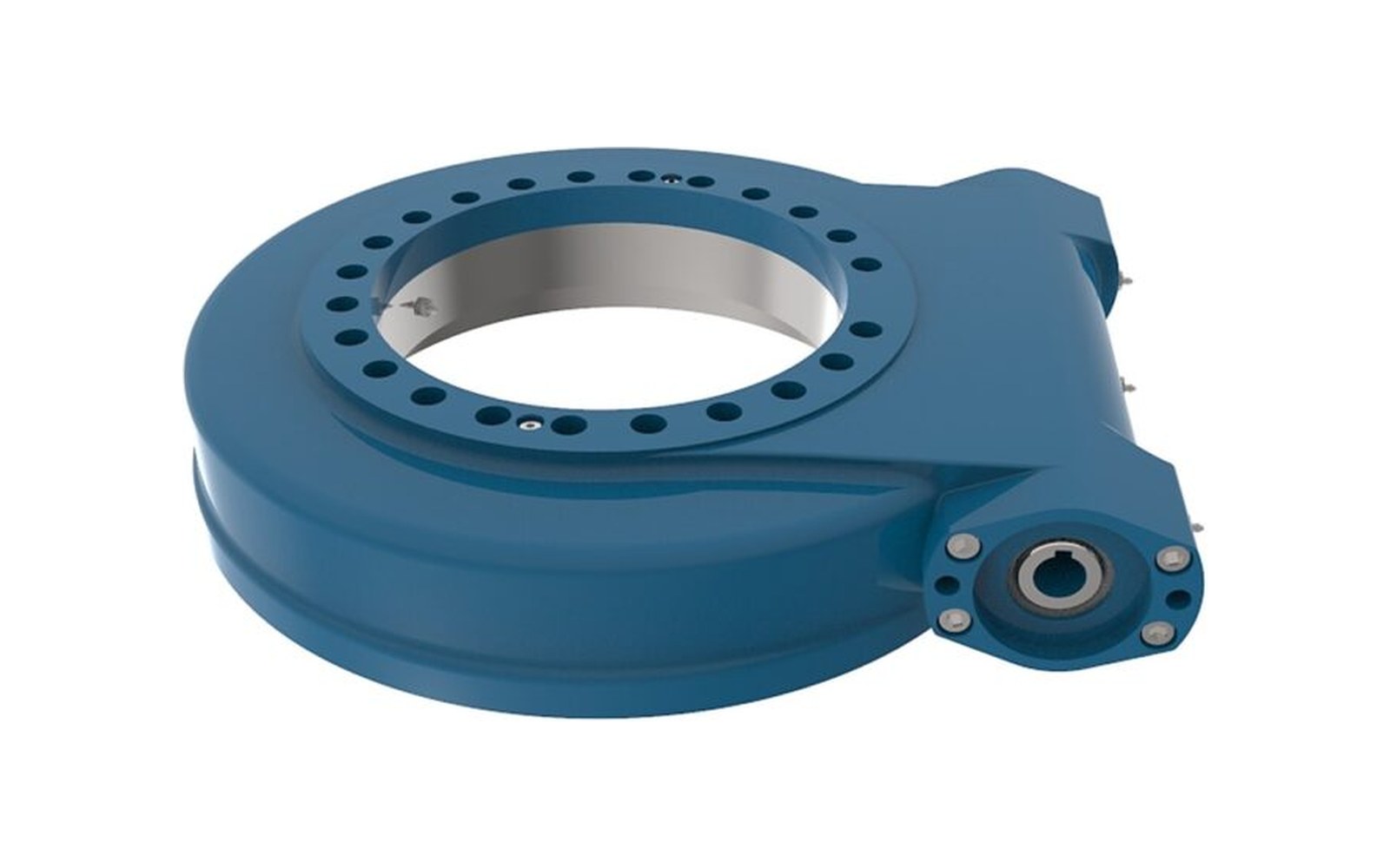
What is a slew drive?
A slew drive is a packaged rotation unit: a slewing ring, a worm shaft and gear, a sealed housing and a motor flange, assembled and run in as one part. Bolt it to the frame, bolt the motor to it, and the machine rotates.
What it replaces is the reason it exists. A bare slewing ring needs a separate gearbox, a pinion, a pinion guard and the alignment work to get the mesh right on site. A slew drive arrives with all of that done at the factory, and — because the worm mesh is self-locking at the usual ratios — it holds the load in position without a brake and without drawing power.
That last point matters more than it sounds. A solar tracker that has to hold its angle through a storm night after night is being held by the worm mesh, not by a brake that wears.
Types of slew drive
Six configurations cover the range. They differ in housing orientation, in the number of worm stages, and therefore in stiffness, backlash and envelope.
| Series | Envelope | Typical use |
|---|---|---|
| VE vertical | Vertical flange | Elevation axis, lift columns |
| S compact | Light housing | Small turntables, single-axis motion |
| WE horizontal | IP65, encoder ready, storm-holding torque | Single-axis solar trackers |
| WED double worm | Two worm stages | Extra rigidity and fine positioning |
| C compact low-backlash | Smallest envelope | Instrument rotation, low-backlash axes |
The distinction that usually decides between them is not the torque rating but the mounting: where the worm shaft enters the housing determines whether the motor can be reached for service.
Features of a slew drive
- Self-locking output. At ratios of 30:1 to 120:1 the worm mesh holds the load when power is removed, so no brake is needed for holding — only for emergency stop if the machine requires it.
- Enveloping worm geometry. The worm is ground to wrap the gear wheel, putting more teeth in mesh than a cylindrical worm in the same envelope. That is where the torque density comes from.
- Sealed to IP65 as standard. The housing is a sealed grease chamber; the failure mode in the field is condensation, not rain, so breathing is designed in.
- Motor interface machined to your drawing. DC gear motor, AC induction with brake, stepper, servo or hydraulic — the flange, pilot, shaft and key are cut to the motor data sheet, so the assembly arrives aligned.
- Holding torque above the back-torque. For outdoor axes we quote holding torque against the wind back-torque at the selected ratio, not against the static load alone.
Applications of slew drives
| Machine | What the drive has to do |
|---|---|
| Construction and truck cranes | Slow, precise slewing with a load held at a radius |
| Aerial work platforms | Rotation of the basket or the turntable |
| Industrial turntables and positioners | Repeatable indexing, low backlash |
| Satellite and radar pedestals | Fine positioning with minimal backlash |
The solar tracker axis is the hardest of these to get right, because the duty cycle is trivial and the life requirement is not: a few degrees of movement per hour, for 25 years, with thermal cycling every day and a storm load a few times a year.
Working principle of a slew drive
The motor turns the worm shaft. The worm, which is a screw with a helical thread, meshes with the bronze gear wheel cut on the slewing ring — a worm gear in the classic sense, wrapped around a bearing. One turn of the worm advances the gear wheel by one tooth, so the reduction ratio is the number of teeth on the wheel divided by the number of worm starts — the reason a single-stage unit reaches 30:1 to 120:1 in a housing that fits in a shoebox.
Two consequences follow from that geometry. First, the contact is sliding rather than rolling, which is why the efficiency is around 40% and why the housing needs a proper grease charge. Second, the lead angle is shallow enough that the gear wheel cannot drive the worm — the mesh locks — which is the self-holding behaviour.
The slewing ring inside the housing carries all the load: axial, radial and moment. The worm carries the torque. The two are set up together at assembly so the backlash is a measured figure on the label, not a promise.
How does a slew drive work in a machine?
The drive bolts to the fixed frame through its flange, and the rotating structure bolts to the ring. Rotation comes from the motor; position comes from an encoder on the motor or, on the WE series, from an encoder mounted in the housing.
Sizing starts from the torque required to rotate the load, then adds the wind or shock back-torque the mesh has to hold, then checks the axial and moment capacity of the ring. The common mistake is to size on the static load and ignore the holding requirement — a drive that rotates the load easily can still be back-driven in a gust if the ratio was chosen for speed.
Slew drives for sale
Drives are quoted from the load and the rotation: torque, output speed, ratio, mounting orientation, motor type and the environment. A motor drawing is enough to confirm the interface; if no motor has been chosen, the torque and speed figures are enough for us to propose a ratio.
Standard sizes in the SE range run from SE5 to SE25, with output torque to 12 kNm continuous and holding torque at 1.5 times the output torque.
Slew drive buying guide
1. Size on holding torque, not only on running torque. For any outdoor axis, the gust case decides the ratio. 2. Check where the worm shaft points. It determines service access and whether the motor fouls the structure. 3. Send the motor drawing before the order, not after. Flange, pilot, shaft, key and bolt circle are the five dimensions that cause most site rework. 4. Decide the encoder with the drive. A drive that needs an encoder later means a new housing or an external bracket. 5. Ask about breathing and sealing, not just the IP number. Condensation inside a sealed housing destroys bearings in the field. 6. Keep a repeatable mounting interface. The same bolt pattern across a tracker row lets a drive be swapped without re-shimming the array.
Slew drive customization
Housing orientation, worm ratio, output flange bolt pattern, shaft keyway, encoder mounting, paint colour and grease grade are all specified per order. Special ratios are ground rather than bought in, so a non-standard reduction is a lead-time question, not a feasibility question.
For retrofit work we machine the output interface to the existing structure, which is often the only way to replace a drive on a machine that is already in service. On the WE and VE frames the worm gear housing itself can be re-machined to accept a different motor standard, which is cheaper than replacing the drive.
Slew drive packaging and shipping
Each drive is greased, run in, sealed in a bag with a desiccant, and packed in a foam-lined carton or a small plywood case depending on size. The label carries the serial number, the ratio, the measured backlash, the grease type and the motor interface dimensions.
Cartons are export-rated and sized for palletising; a full tracker row ships on one pallet with the drives in the order they are to be fitted.
Slew drive manufacturer
The ring, the worm and the housing are matched and run in as one unit rather than assembled from bought-in parts. Housings are ductile iron with a sealed grease chamber; worms are ground after heat treatment; rings are induction hardened and the raceway hardness is recorded per batch.
The range covers six configurations with output torque to 12 kNm and holding torque at 1.5 times output, sealed to IP65 with IP66 available for washdown or coastal sites.
FAQ
Is a slew drive self-locking in both directions?
Yes at the standard ratios. At very low ratios on the double-worm series the mesh can be back-driven under shock, which is why the holding case is quoted explicitly rather than assumed.
Worm gear or spur gear, which is better for a rotating axis?
Worm where the axis has to hold position with the power off, at the cost of efficiency. Spur where torque density and speed matter more, with a brake and an encoder added to hold position.
Can I fit my own motor?
Yes, provided the flange, pilot, shaft and key match. Send the motor drawing and we cut the interface to it; fitting a motor with a different pilot later needs an adapter.
What maintenance does it need?
A grease check at the interval on the label, and a seal inspection if the drive runs in dust or salt air. There is no oil to change.
How long is the lead time?
Standard ratios in four to six weeks; special ratios and custom interfaces add two to three weeks for grinding and inspection.
Tell us the torque and the rotation, and send the motor drawing if you have one.
Send your drive enquiry