Category: Knowledge

  • Three-Row Roller Slewing Bearing: Structure, Load Capacity and Selection

    Three-Row Roller Slewing Bearing: Structure, Load Capacity and Selection

    What is a three-row roller slewing bearing?

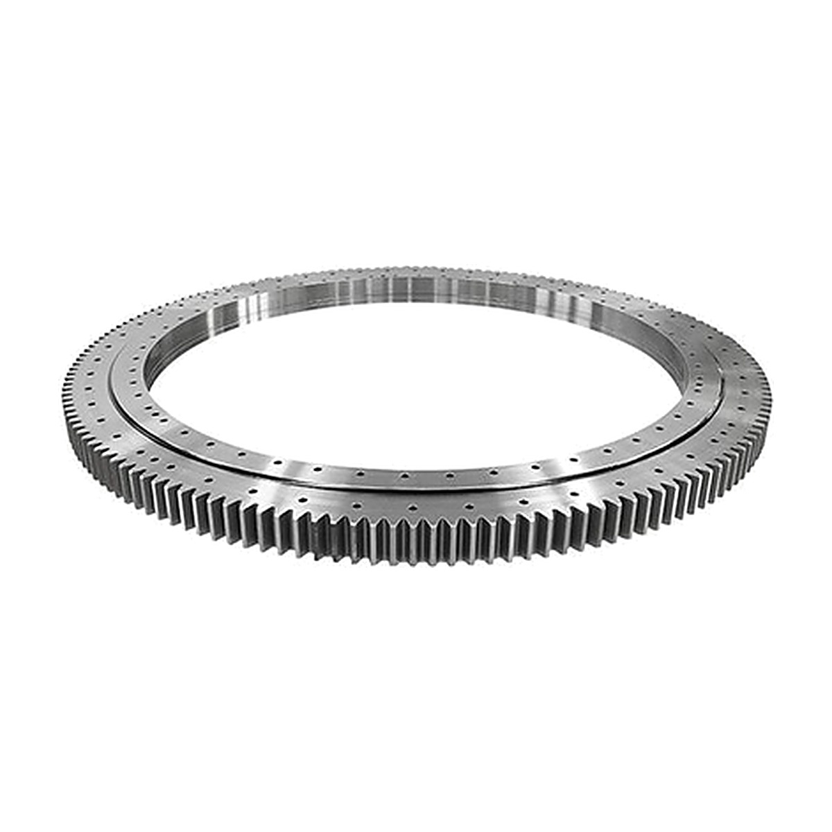
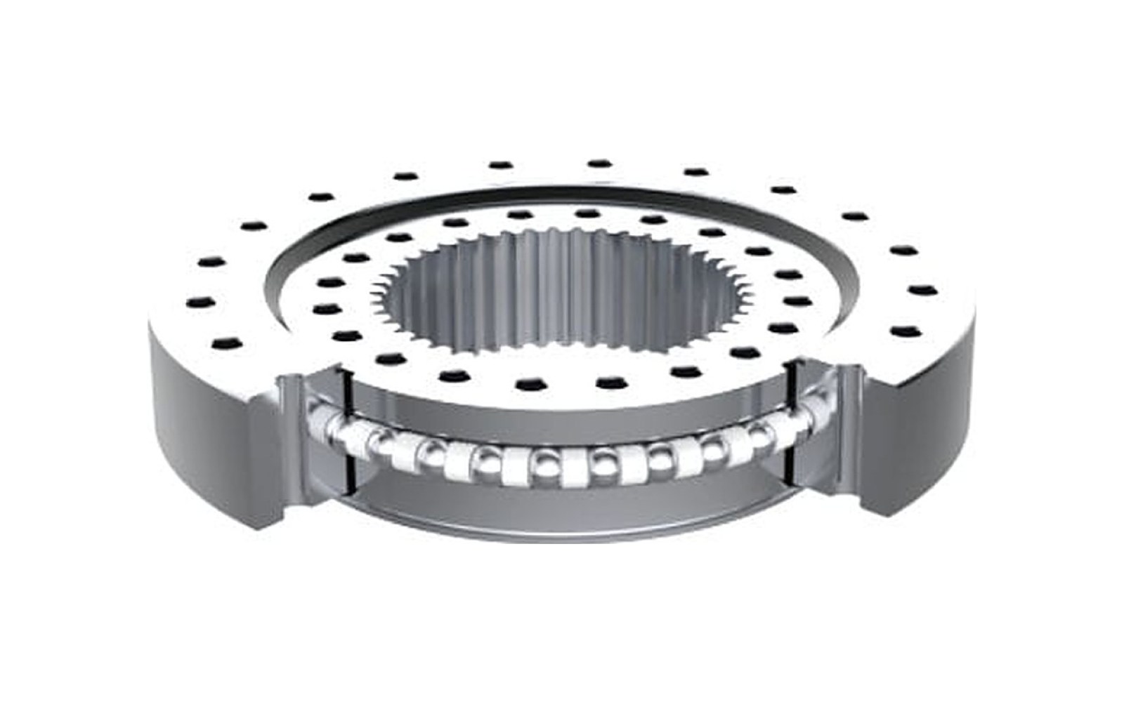
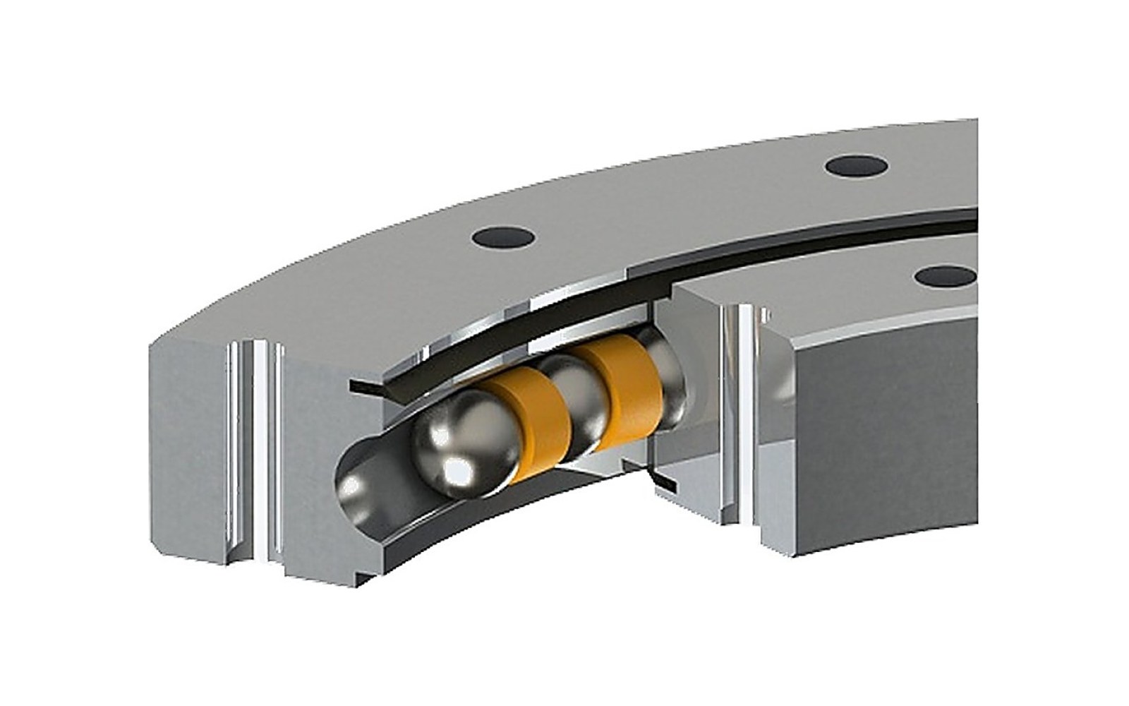
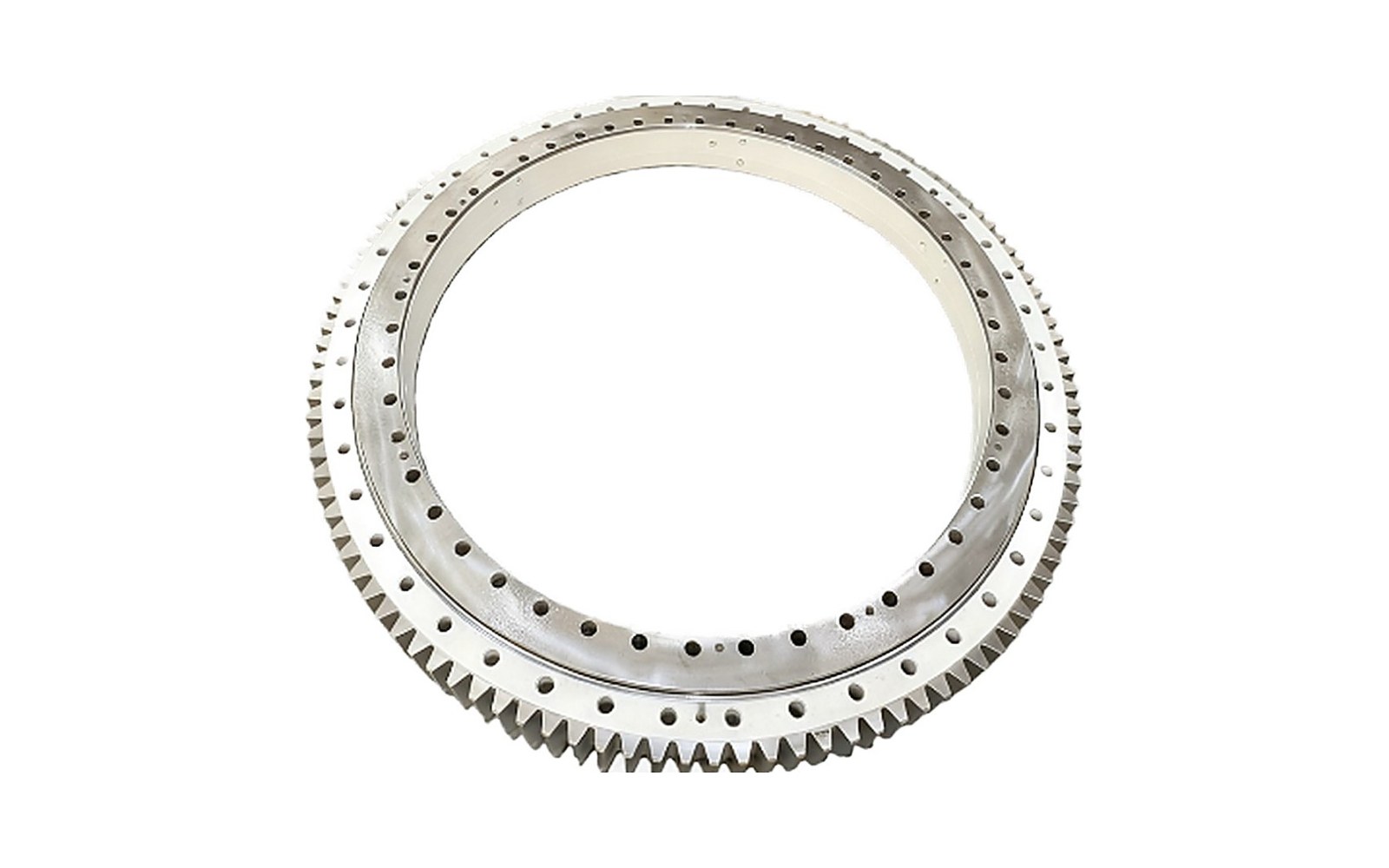
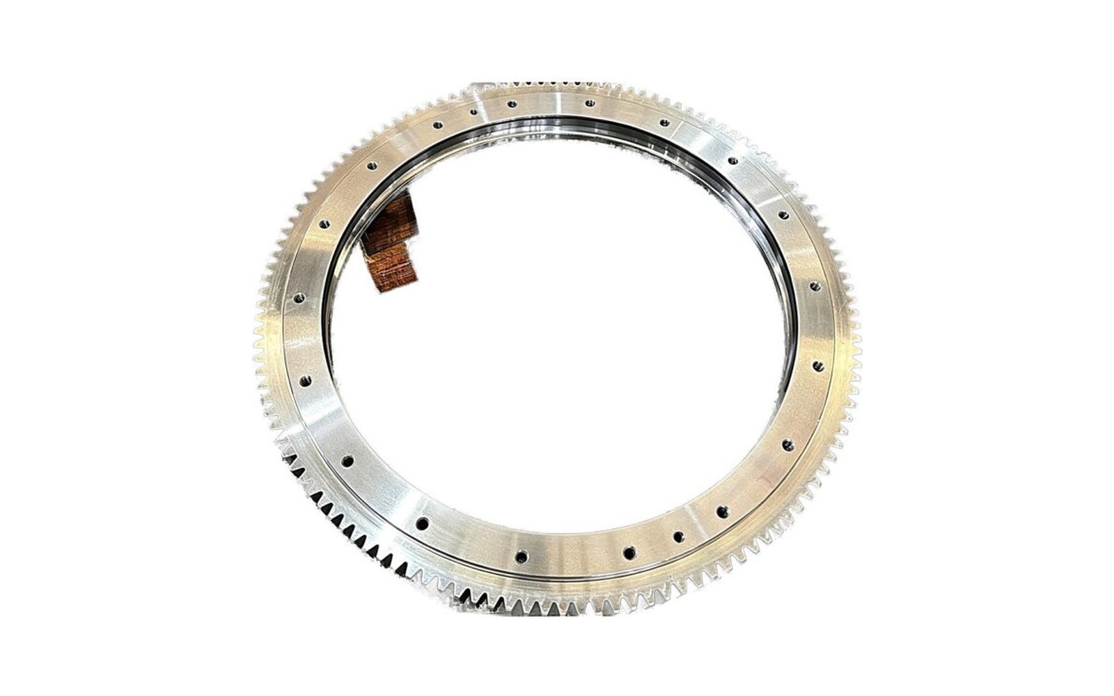
    A three-row roller slewing bearing is a slewing ring built with three separate raceways: an upper axial row, a lower axial row and a vertical radial row. Each raceway has its own set of cylindrical rollers, and each is loaded only in the direction it was designed for.

    That separation is the whole idea. In a single-raceway ball ring, one contact has to resolve axial load, radial load and tilting moment together, so the ball size and the raceway geometry are a compromise. Splitting the load paths lets each row be optimised, and the capacity that comes out of the same diameter is far higher.

    In our range the structure runs from 500 mm to 6,000 mm outside diameter, with section heights of 106 mm to 300 mm — the tallest structure we make, and the one we propose as standard above about two metres.

    Types of three-row roller slewing bearing

    The three rows are stacked, not mixed. The upper and lower axial rows take axial load in both directions and, because they sit at a distance from each other, the tilting moment as a couple. The vertical row takes radial load only.

    VariantGearTypical machine
    External gear three-row rollerTeeth on the outer diameter, module 6–25Stacker-reclaimers, deck cranes, large turntables
    Internal gear three-row rollerTeeth in the boreExcavators and machines where the mesh must be protected

    Gearing is a machining operation on top of the structure, not a separate family. All three variants share the same raceway arrangement, the same hardening and the same sealing options.

    Features of a three-row roller slewing bearing

    • Highest capacity per unit of diameter in the range. Static axial rating to 12,000 kN, radial to 3,000 kN, tilting moment to 5,000 kNm.
    • Load paths kept apart. Each row is loaded in one direction, so the rollers and the raceway geometry are sized for that direction rather than for a compromise.
    • Induction hardened raceways with the soft zone marked and positioned away from the loaded arc.
    • Gear to module 25, induction hardened to 50–58 HRC on the teeth, available externally or internally.
    • Double-lip NBR seals as standard, Viton on request for hot or aggressive environments.
    • Split ring option for structures that cannot be threaded over a shaft.

    Applications of three-row roller bearings

    Three-row roller rings turn up wherever the load is heavy and continuous rather than occasional: bulk-handling terminals head the list, closely followed by deck cranes and ladle turrets.

    MachineWhy this structure
    Deck cranes and quay cranesHeavy axial load combined with a long moment arm
    Ladle turrets and converter ringsHigh load at temperature, with thermal growth designed in
    Large excavators and mining shovelsShock load plus an eccentric working radius
    Wind turbine yaw systems (large frames)Moment-dominated load with a long service life

    Below two metres the three-row structure is often more capacity than the machine needs, and a four-point contact or double row ball ring does the same job in less height and at lower cost.

    Working principle of a three-row roller bearing

    Load enters through the bolt circle of one ring and leaves through the bolt circle of the other. Between them, the rollers distribute it across the three raceways.

    An axial load pushes the upper ring down. The upper axial row takes the load in one direction; reverse the load and the lower row takes it. A tilting moment loads the upper row on one side and the lower row on the opposite side — the two rows form a couple whose lever arm is the distance between them, which is why the tall section is an advantage rather than a compromise. A radial load goes into the vertical row, whose rollers run on a cylindrical path at the outside diameter of the inner ring.

    Rotation comes from either the gear, when fitted, or a separate drive. The cage or spacer keeps the rollers evenly spaced around the perimeter so the load is shared rather than concentrated at the point where the load enters.

    How does a three-row roller bearing work in a machine?

    The ring bolts to a machined flange at top and bottom. Flatness and bolt preload matter more here than on a ball ring, because a three-row ring is stiff enough that it will not absorb a badly machined flange — the flange will deflect the ring instead, and the load will concentrate on part of the raceway.

    Because the section is tall, the ring also takes up vertical space in the design. That is the trade: the capacity is bought with height, and a machine that is height-limited cannot use it, however attractive the load rating looks on paper.

    Load capacity

    The three ratings are quoted separately because they are governed by different failure modes.

    RatingFigure in this rangeWhat it governs
    Static radialto 3,000 kNRadial row deformation under side load
    Static tilting momentto 5,000 kNmThe couple across the two axial rows; usually the figure that decides the size

    For continuously rotating equipment the static ratings are only a starting point. Above a few hundred thousand load cycles per year the ring has to be sized on the fatigue life of the raceway, which depends on the load spectrum and the hardened depth rather than on the catalogue figures.

    Three-row roller slewing bearing for sale

    Rings are quoted per drawing or per load case. Send the outside diameter, raceway centre diameter, section height, hole pattern, gear module and the three load figures; if the machine already exists, send the old part number and we will reverse-engineer the drawing.

    Standard sizes are held for the common diameters, with larger and non-standard rings machined to order.

    Three-row roller bearing buying guide

    1. Check that the structure is right before the size. If the load is moment-dominated and the machine has height to spare, three-row roller is the answer; if not, a ball ring in less height may be better. 2. Size on the moment. The axial rating looks impressive and is rarely the binding constraint. 3. Ask for the hardened depth with the hardness figure. Hardness without depth does not tell you whether the raceway will survive the load cycles. 4. Decide internal or external gear early. It changes the pinion position, the guard and the service access. 5. Check mounting flatness and bolt class. A stiff ring will not forgive a soft flange. 6. Consider a split ring if the structure cannot be dismantled to fit a one-piece ring over a shaft.

    Three-row roller slewing bearing customization

    Non-standard bolt patterns, split rings, special grease channel positions, tapped holes in the flange face, alternative seal materials, phosphate or painted finish, and gear teeth cut to a mating pinion sample are all machined to order. Rings can also be supplied with the soft zone positioned to a specified angle when the loaded arc is known.

    Three-row roller slewing bearing packaging and shipping

    Three-row roller rings above about 1.2 m ship upright in a plywood case with the raceway face protected and lifting points marked. The case carries the inspection record with measured hardness, hardened depth, clearance and gear backlash, plus the grease specification.

    Large rings are lifted with a spreader beam, never with a sling through the bore, and the packing is photographed before the case is closed.

    Three-row roller slewing bearing manufacturer

    Three-row roller rings are machined, induction hardened, ground and assembled in one plant, which is what allows the hardened depth and the clearance to be quoted with a batch reference attached.

    The range covers 500 mm to 6,000 mm outside diameter, section heights of 106 mm to 300 mm, gearing to module 25 both internal and external, and a static capacity to 12,000 kN axial.

    FAQ of three-row roller slewing bearing

    Where can I buy a three-row roller slewing bearing?

    Rings are quoted per drawing or per load case, either as a standard diameter from stock or machined to order. Send the outside diameter, section height, gear module and the three load figures and the quotation comes back with the structure confirmed.

    When should I choose three-row roller over four-point contact?

    When the load is heavy and sustained, or when the moment is large enough that a ball ring would need a diameter the machine cannot accommodate. If height is the binding constraint, stay with the ball structure.

    Can the rows be re-lubricated separately?

    Yes. Grease channels are positioned per row, and on large rings we specify the nipple positions so each row can be reached without dismantling the machine.

    What is the soft zone on a three-row roller ring and why does it matter?

    It is the unhardened strip left where the filling plug and the hardening inductor start and stop. It is positioned away from the loaded arc; if a ring is fitted rotated, that strip can end up in the load path.

    Is a split three-row roller ring as strong as a one-piece ring?

    The split is bolted and pinned across the section, so capacity is close but not identical. It is used where the structure cannot be threaded over a shaft, not as a default.

    What lead time should I plan for?

    Standard diameters four to six weeks; above 3 m and for split rings, eight to ten weeks including the inspection record.

    Send the three load figures and the mounting space, and we will confirm whether a three-row roller ring is the right structure.

    Send your load case
  • Slew Drive: Types, Working Principle, Applications and Buying Guide

    Slew Drive: Types, Working Principle, Applications and Buying Guide

    What is a slew drive?

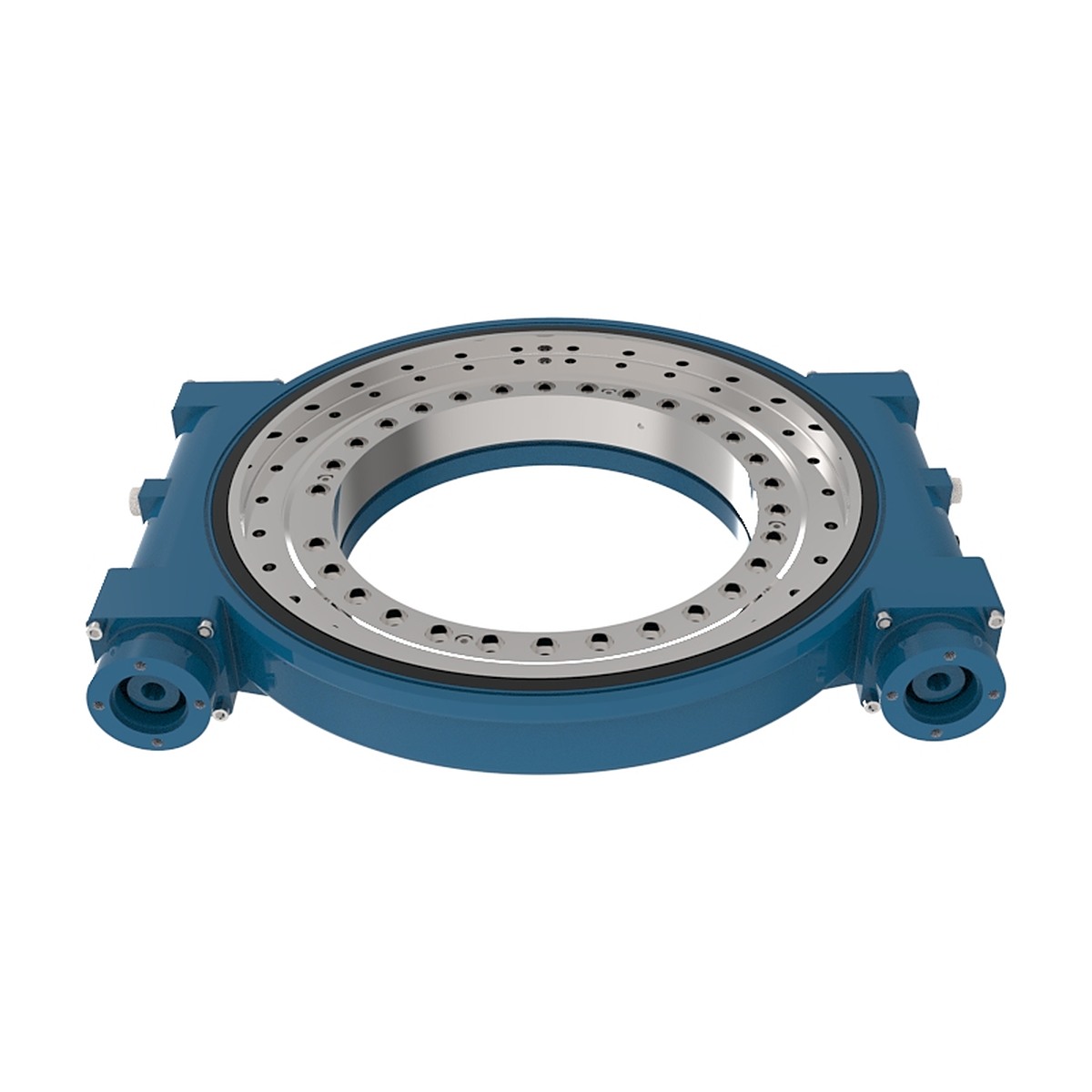
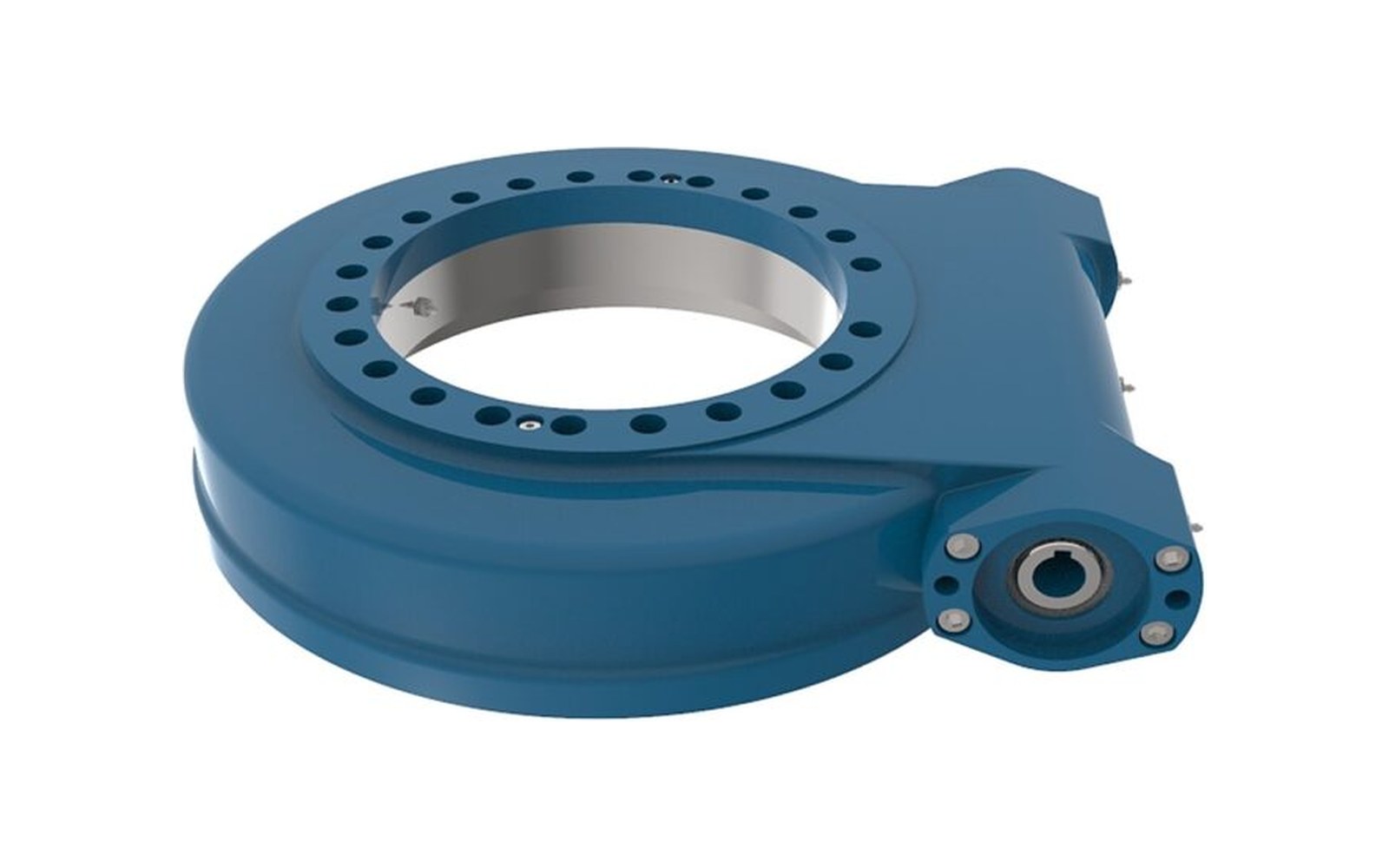
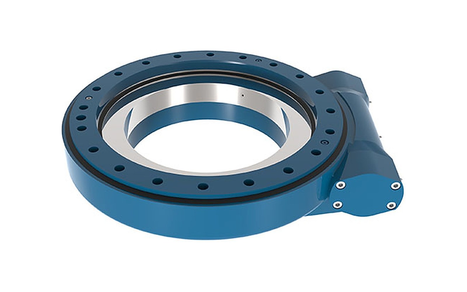
    A slew drive is a packaged rotation unit: a slewing ring, a worm shaft and gear, a sealed housing and a motor flange, assembled and run in as one part. Bolt it to the frame, bolt the motor to it, and the machine rotates.

    What it replaces is the reason it exists. A bare slewing ring needs a separate gearbox, a pinion, a pinion guard and the alignment work to get the mesh right on site. A slew drive arrives with all of that done at the factory, and — because the worm mesh is self-locking at the usual ratios — it holds the load in position without a brake and without drawing power.

    That last point matters more than it sounds. A solar tracker that has to hold its angle through a storm night after night is being held by the worm mesh, not by a brake that wears.

    Types of slew drive

    Six configurations cover the range. They differ in housing orientation, in the number of worm stages, and therefore in stiffness, backlash and envelope.

    SeriesEnvelopeTypical use
    VE verticalVertical flangeElevation axis, lift columns
    S compactLight housingSmall turntables, single-axis motion
    WE horizontalIP65, encoder ready, storm-holding torqueSingle-axis solar trackers
    WED double wormTwo worm stagesExtra rigidity and fine positioning
    C compact low-backlashSmallest envelopeInstrument rotation, low-backlash axes

    The distinction that usually decides between them is not the torque rating but the mounting: where the worm shaft enters the housing determines whether the motor can be reached for service.

    Features of a slew drive

    • Self-locking output. At ratios of 30:1 to 120:1 the worm mesh holds the load when power is removed, so no brake is needed for holding — only for emergency stop if the machine requires it.
    • Enveloping worm geometry. The worm is ground to wrap the gear wheel, putting more teeth in mesh than a cylindrical worm in the same envelope. That is where the torque density comes from.
    • Sealed to IP65 as standard. The housing is a sealed grease chamber; the failure mode in the field is condensation, not rain, so breathing is designed in.
    • Motor interface machined to your drawing. DC gear motor, AC induction with brake, stepper, servo or hydraulic — the flange, pilot, shaft and key are cut to the motor data sheet, so the assembly arrives aligned.
    • Holding torque above the back-torque. For outdoor axes we quote holding torque against the wind back-torque at the selected ratio, not against the static load alone.

    Applications of slew drives

    MachineWhat the drive has to do
    Construction and truck cranesSlow, precise slewing with a load held at a radius
    Aerial work platformsRotation of the basket or the turntable
    Industrial turntables and positionersRepeatable indexing, low backlash
    Satellite and radar pedestalsFine positioning with minimal backlash

    The solar tracker axis is the hardest of these to get right, because the duty cycle is trivial and the life requirement is not: a few degrees of movement per hour, for 25 years, with thermal cycling every day and a storm load a few times a year.

    Working principle of a slew drive

    The motor turns the worm shaft. The worm, which is a screw with a helical thread, meshes with the bronze gear wheel cut on the slewing ring — a worm gear in the classic sense, wrapped around a bearing. One turn of the worm advances the gear wheel by one tooth, so the reduction ratio is the number of teeth on the wheel divided by the number of worm starts — the reason a single-stage unit reaches 30:1 to 120:1 in a housing that fits in a shoebox.

    Two consequences follow from that geometry. First, the contact is sliding rather than rolling, which is why the efficiency is around 40% and why the housing needs a proper grease charge. Second, the lead angle is shallow enough that the gear wheel cannot drive the worm — the mesh locks — which is the self-holding behaviour.

    The slewing ring inside the housing carries all the load: axial, radial and moment. The worm carries the torque. The two are set up together at assembly so the backlash is a measured figure on the label, not a promise.

    How does a slew drive work in a machine?

    The drive bolts to the fixed frame through its flange, and the rotating structure bolts to the ring. Rotation comes from the motor; position comes from an encoder on the motor or, on the WE series, from an encoder mounted in the housing.

    Sizing starts from the torque required to rotate the load, then adds the wind or shock back-torque the mesh has to hold, then checks the axial and moment capacity of the ring. The common mistake is to size on the static load and ignore the holding requirement — a drive that rotates the load easily can still be back-driven in a gust if the ratio was chosen for speed.

    Slew drives for sale

    Drives are quoted from the load and the rotation: torque, output speed, ratio, mounting orientation, motor type and the environment. A motor drawing is enough to confirm the interface; if no motor has been chosen, the torque and speed figures are enough for us to propose a ratio.

    Standard sizes in the SE range run from SE5 to SE25, with output torque to 12 kNm continuous and holding torque at 1.5 times the output torque.

    Slew drive buying guide

    1. Size on holding torque, not only on running torque. For any outdoor axis, the gust case decides the ratio. 2. Check where the worm shaft points. It determines service access and whether the motor fouls the structure. 3. Send the motor drawing before the order, not after. Flange, pilot, shaft, key and bolt circle are the five dimensions that cause most site rework. 4. Decide the encoder with the drive. A drive that needs an encoder later means a new housing or an external bracket. 5. Ask about breathing and sealing, not just the IP number. Condensation inside a sealed housing destroys bearings in the field. 6. Keep a repeatable mounting interface. The same bolt pattern across a tracker row lets a drive be swapped without re-shimming the array.

    Slew drive customization

    Housing orientation, worm ratio, output flange bolt pattern, shaft keyway, encoder mounting, paint colour and grease grade are all specified per order. Special ratios are ground rather than bought in, so a non-standard reduction is a lead-time question, not a feasibility question.

    For retrofit work we machine the output interface to the existing structure, which is often the only way to replace a drive on a machine that is already in service. On the WE and VE frames the worm gear housing itself can be re-machined to accept a different motor standard, which is cheaper than replacing the drive.

    Slew drive packaging and shipping

    Each drive is greased, run in, sealed in a bag with a desiccant, and packed in a foam-lined carton or a small plywood case depending on size. The label carries the serial number, the ratio, the measured backlash, the grease type and the motor interface dimensions.

    Cartons are export-rated and sized for palletising; a full tracker row ships on one pallet with the drives in the order they are to be fitted.

    Slew drive manufacturer

    The ring, the worm and the housing are matched and run in as one unit rather than assembled from bought-in parts. Housings are ductile iron with a sealed grease chamber; worms are ground after heat treatment; rings are induction hardened and the raceway hardness is recorded per batch.

    The range covers six configurations with output torque to 12 kNm and holding torque at 1.5 times output, sealed to IP65 with IP66 available for washdown or coastal sites.

    FAQ

    Is a slew drive self-locking in both directions?

    Yes at the standard ratios. At very low ratios on the double-worm series the mesh can be back-driven under shock, which is why the holding case is quoted explicitly rather than assumed.

    Worm gear or spur gear, which is better for a rotating axis?

    Worm where the axis has to hold position with the power off, at the cost of efficiency. Spur where torque density and speed matter more, with a brake and an encoder added to hold position.

    Can I fit my own motor?

    Yes, provided the flange, pilot, shaft and key match. Send the motor drawing and we cut the interface to it; fitting a motor with a different pilot later needs an adapter.

    What maintenance does it need?

    A grease check at the interval on the label, and a seal inspection if the drive runs in dust or salt air. There is no oil to change.

    How long is the lead time?

    Standard ratios in four to six weeks; special ratios and custom interfaces add two to three weeks for grinding and inspection.

    Tell us the torque and the rotation, and send the motor drawing if you have one.

    Send your drive enquiry
  • Slewing Bearing: Types, Working Principle, Applications and Buying Guide

    Slewing Bearing: Types, Working Principle, Applications and Buying Guide

    What is a slewing bearing?

    A slewing bearing — also called a turntable bearing or swing circle — is a large-diameter rolling bearing (also written slewing ring) that lets two parts of a machine rotate relative to each other while carrying load in three directions at the same time: axial load, radial load and tilting moment.

    A slewing ring is the same part under its older name, and the two terms are used interchangeably in drawings and purchase orders.

    That combination is what separates it from an ordinary bearing. A standard ball bearing is built to carry load in one direction and is mounted in a housing that takes care of the rest. A slewing bearing has no housing. The mounting bolt circle is the housing, the gear teeth may be cut into the ring itself, and the whole assembly is often a structural member of the machine — an excavator swing circle, a crane slew ring, the rotation joint under a solar tracker.

    Most rings are supplied as two machined rings with a row of balls or rollers between them, a seal on each side, grease nipples, and a gear cut on the outside or inside diameter. Outside diameters in our range run from 100 mm to 6 m, and everything above that is quoted individually.

    Types of slewing bearing

    Seven structures cover almost every enquiry we receive. The differences are the number of raceways, the rolling element, and therefore the capacity-to-height ratio. The seven are listed below, starting with the four-point contact ball ring that most swing circles use and finishing with the geared and flanged variants.

    StructureLoad pathTypical strength
    Crossed rollerCylindrical rollers crossed at 90 degrees in one racewayHigh stiffness, minimal deflection
    Double row ballTwo ball rows with separate racewaysHigher tilting capacity than single row
    Three-row roller (13 series)Two axial raceways plus one radial racewayHighest capacity we make
    External gearAny of the above with teeth on the outer diameterPinion can sit anywhere on the perimeter
    Internal gearAny of the above with teeth in the boreMesh protected inside the structure
    Flanged / light seriesIntegral flange, or a thin reduced sectionFewer parts, or lower weight

    Gearing is not a separate structure — it is applied on top of one. Any ring can be supplied plain, with external teeth, or with internal teeth. The same applies to hardening: raceways are induction hardened as standard, and the hardened depth is quoted per application rather than taken from a catalogue table.

    Features of a slewing bearing

    • Three loads through one joint. Axial, radial and moment capacity are quoted together, because a ring that is strong axially but weak in moment will still fail on a cantilevered boom.
    • The ring is the structure. Bolt circles, counterbores, grease passages and gear teeth are all machined into the ring, so the machine has one part fewer and one joint fewer than a bearing-plus-housing design.
    • Induction hardened raceways. 42CrMo4 or 50Mn rings, raceway hardness typically 55–62 HRC, with the soft zone — the unhardened strip left where the filling plug goes — positioned away from the loaded arc.
    • Sealing quoted explicitly. Double-lip NBR as standard, Viton for high temperature. The seal, not the steel, is usually what ends a ring’s life in the field.
    • Clearance and preload set to the drawing. Normal, reduced or preloaded, because a positioning axis and a swing circle need different answers from the same ring.

    Applications of slewing bearings

    MachineWhy a slewing ring fits
    Solar trackersSlow rotation, long life, low starting torque
    Port and shipyard cranes, stacker-reclaimersContinuous rotation under heavy axial load; fatigue life governs, not static capacity
    Machine tools, rotary tables, positionersPosition has to be held; crossed roller rings are chosen for stiffness
    Ladle turrets, convertersHeat-stabilised rings, high-temperature grease, thermal growth designed in

    Size is only half the decision. The same 1,000 mm ring can be right for a crane and wrong for an excavator, because the duty cycle, the shock load and the environment decide the structure, the hardening depth and the sealing.

    Working principle of a slewing bearing

    The ring carries load through a single closed raceway. In a four-point contact ring the raceway is ground to a Gothic arch, so one ball touches it at four points: two on the outer ring, two on the inner ring. Axial load in either direction, radial load and tilting moment all resolve into those four contact points, which is why the structure can be so thin.

    Rotate the ring and the balls roll along the raceway, separated by a cage or spacer that keeps them evenly spaced. Grease sits in the raceway groove and is pushed around by the balls themselves, which is why a correctly filled ring can run for long intervals without re-lubrication — and why an over-greased ring can blow a seal.

    The gear, when fitted, is a separate load path: a pinion meshes with the teeth on the ring and drives rotation. The bearing carries the load, the gear carries the torque, and the two are machined in the same setup so the pitch circle runs true to the raceway.

    How does a slewing bearing work in a machine?

    Mounting is where most rings are lost. The flange the ring bolts to has to be flat and stiff enough that it does not deflect under load and concentrate the load on part of the raceway. Bolts have to be preloaded to the figure on the drawing, not torqued to feel. Water has to drain away from the seal, not into it.

    The crossed roller structure is the more forgiving choice when the flange cannot be made stiff enough, because each roller contacts along its full length instead of at four points.

    Get those three right and the ring runs for years with an annual grease check. Get them wrong and the raceway spalls in a season, which is why we ask for the mounting flatness and bolt class with every enquiry rather than after the first failure.

    Slewing bearings for sale

    Rings are quoted per drawing. Send the outside diameter, bore, raceway centre diameter, section height, hole pattern, gear module and tooth count, plus the axial, radial and moment figures. If the drawing does not exist yet, send the machine, the load and the rotation and we will propose a structure and a size.

    Standard sizes are kept in stock for the common four-point contact and three-row roller ranges; anything outside those is machined to order, typically four to six weeks for a first article.

    Slewing bearing buying guide

    1. Start from the moment, not the diameter. Tilting moment usually decides the structure; the diameter then follows from the mounting space. 2. Check the available section height. If the design is height-limited, four-point contact or crossed roller; if capacity-limited, three-row roller. 3. Decide the gear before the drawing is frozen. Internal, external or plain changes the ring, the pinion position and the guard. 4. Specify the environment. Salt air, abrasive dust and radiant heat each change the seal, the grease and sometimes the material. 5. Ask for the inspection record. Raceway hardness, hardened depth, clearance and gear backlash should arrive as measured values with a batch reference. 6. Price the mounting, not just the ring. A cheaper ring on a machined adapter plate can cost more than a flanged ring that bolts straight on.

    Slewing bearing customization

    Everything that is not a standard size is machined to drawing: non-standard bolt patterns, split rings for structures that cannot be threaded over a shaft, special grease nipple positions, tapped holes in the flange face, phosphate or painted finish, and gear teeth cut to a mating pinion sample.

    We machine the mounting flange and the raceway in the same setup, so runout on the flange face stays inside 0.05 mm. Drawings in PDF, DWG or STEP are all workable.

    Slewing bearing packaging and shipping

    Rings up to about 1.2 m ship in a plywood case with the ring bolted to a pallet base so it cannot rock in transit. Larger rings are crated upright with the raceway face protected and lifting points marked. Every case carries the inspection record, the packing list and a grease specification sheet.

    Sea freight is standard for export; air freight is used for urgent spares and for rings small enough to travel as air cargo. We photograph the packing before the case is closed so the condition on arrival can be checked against it.

    Slewing bearing manufacturer

    Rings are machined, hardened, ground and assembled in one plant, which is what makes it possible to quote the hardened depth and the clearance with the batch reference attached. Heat treatment is induction hardening in-house, followed by tempering and a hardness check on every batch rather than a sample.

    The range covers outside diameters from 100 mm to 6 m across the seven structures, with gearing, sealing and clearance selected per application. Custom and reverse-engineered rings — matched to an old part number with no drawing available — are a regular part of the work.

    FAQ

    How do I choose between a slewing bearing and a plain turntable?

    If the joint has to carry load in three directions and hold position, a rolling ring is the lower-friction, longer-life answer. A plain bearing only makes sense for very slow, lightly loaded rotation where cost dominates.

    Can a slewing bearing be repaired?

    Raceways cannot be re-ground in the field. A ring that has spalled is replaced. What can be done is to re-seal and re-grease a ring that is still sound, which is worth doing on large rings where replacement means lifting the structure.

    What is the smallest ring you make?

    The light series starts at 100 mm outside diameter with a 20 mm section; below that a crossed roller instrument bearing is usually the better answer.

    How long does a ring last?

    It depends on the load spectrum and the sealing. A well-sealed ring at rated load typically reaches tens of thousands of hours of rotation; a ring running in abrasive dust with a damaged seal can fail in a single season.

    Do you supply the pinion as well?

    Yes. Sending the ring drawing with the pinion sample or the gear data lets us match the backlash and the tooth hardness together.

    Send the ring drawing, or the load case if there is no drawing yet.

    Send your drawing
  • Four-point contact or crossed roller: which one to specify

    Four-point contact or crossed roller: which one to specify

    These two structures are the most common source of confusion in a first enquiry, because both are described as handling combined loads. They do — but not equally well, and not at the same cost.

    Four-point contact ball

    A single row of balls contacts a Gothic-arch raceway at four points, so one bearing takes axial load in both directions, radial load and tilting moment. It is the thinnest option, the cheapest per unit of diameter, and the usual choice for solar trackers, small cranes and light turntables.

    • Best for: moderate loads, tight height, cost-sensitive projects.
    • Watch out for: it is more sensitive to mounting flange stiffness than a roller bearing. A thin, flexible flange will deflect and load only part of the raceway.

    Crossed cylindrical roller

    Cylindrical rollers sit at 90° to each other in a single raceway, so the contact is line contact rather than point contact. Stiffness is higher and the bearing tolerates heavier and more eccentric loads, at the cost of a taller section.

    • Best for: heavy axial or moment load, machine tools, positioners where deflection matters.
    • Watch out for: cost, and a taller stack height that may not fit an existing design.

    A quick rule

    If height is the binding constraint and the load is moderate, take four-point contact. If deflection under load is what you are trying to control, take crossed roller — and expect to pay for it.

    Give us the axial, radial and moment figures and we will tell you which structure fits.

    Send your load case
  • Internal gear, external gear, or no-gear slew bearing

    Internal gear, external gear, or no-gear slew bearing

    A slewing bearing is often described by its gear: internal, external or ungeared. The choice is usually made early and then constrains everything downstream.

    External gear

    Teeth on the outside of the outer ring. The pinion sits outside the bearing envelope, which makes it easy to service and easy to retrofit. The trade-off is a larger swept envelope — the drive train sticks out and needs guarding.

    Internal gear

    Teeth on the inside of the outer ring. The pinion sits inside the bore, so the assembly is more compact and better protected. It is the common choice for excavators and cranes where the drive must not be exposed. Mounting and shimming are more awkward because the pinion is harder to reach.

    No gear

    An ungeared bearing is used when rotation comes from somewhere else — a separate drive, a hydraulic motor on a chain, or when the ring is structural only. It is the cheapest option and often the right one.

    What we need to quote a geared ring

    • Module, number of teeth and pressure angle, or the centre distance and pinion data.
    • Required backlash and whether the pinion is supplied by you or by us.
    • Hardness requirement on the teeth.

    Module, teeth and backlash are enough to start.

    Send the gear data
  • How to size a slew drive without over-specifying it

    How to size a slew drive without over-specifying it

    Slew drives are usually over-specified, and it is rarely the engineer’s fault — the three rating numbers on a datasheet are easy to mix up.

    Output torque vs holding torque

    Output torque is what the drive can turn against. Holding torque is what it can resist when stationary, and it is much higher because the worm gear is self-locking. If your load is mostly static — a tilted solar array holding position against wind — the holding figure is the one that matters, and a smaller drive will do.

    Tilting moment

    This is the moment trying to tip the bearing over, usually the dominant load on a solar tracker in stow position. It is limited by the bearing inside the drive, not by the gear, so it does not improve by choosing a bigger motor.

    Duty cycle

    A drive that moves twice a day and a drive that sweeps continuously have very different thermal lives. Tell us the moves per day and the arc of travel; it changes the recommendation more than the peak torque does.

    Enclosure and environment

    IP rating, temperature range and whether the site has sand or salt. These are cheap to specify correctly and expensive to fix later.

    Send the load, the arc and the moves per day.

    Ask for a sizing check
  • Grease: how much, how often, and what goes wrong

    Grease: how much, how often, and what goes wrong

    When a returned bearing shows raceway spalling, the first question is not what the steel was — it is how it was greased.

    The failure pattern

    Under-greasing starves the contact and produces fine pitting that grows into spalling. Over-greasing is also a problem: excess grease blows out the seal, and once the seal is gone on a dusty site the bearing is finished.

    A practical interval

    As a starting point, grease every 100 operating hours for normal conditions, and every 50 hours for dusty, wet or high-temperature sites. For a solar tracker that moves a few times a day, this often works out to a service visit every six months — which is what most operators do anyway.

    • Rotate the bearing while greasing so the new grease is distributed.
    • Wipe the nipple before coupling to avoid pushing grit in.
    • Stop when fresh grease appears at the seal — not before, not much after.

    What to specify

    Tell us the ambient temperature range and whether the site is coastal. Lithium complex EP grease covers most cases; extremely cold sites need a different base oil.

    We can send the recommended grease and interval for your model.

    Ask for a lubrication sheet
  • Mounting flatness and bolt preload: the two numbers that decide service life

    Mounting flatness and bolt preload: the two numbers that decide service life

    A bearing is only as round as the structure it is bolted to. Two mounting numbers account for a large share of the early failures we are asked to investigate.

    Flange flatness

    The mounting surface should be flat within roughly 0.1 mm over the full diameter for a machined flange, and the two surfaces — upper and lower — should be parallel. Welded structures usually need machining after welding, not before.

    Bolt preload

    Bolts hold the ring to the flange and carry the separating load. If they are not preloaded to the specified torque, the ring lifts cyclically, the raceway is loaded unevenly, and the bolts themselves fatigue.

    • Use the torque in the drawing, applied with a calibrated wrench, in a cross pattern in two passes.
    • Check bolt grade. A grade 8.8 bolt substituted for 10.9 changes the required torque.
    • Re-check torque after the first week of operation, then at each service.

    A quick field check

    With the bearing unloaded, rotate it by hand. A ring that binds at one position is usually telling you the flange is out of flat, not that the bearing is defective.

    We will mark the flatness and torque callouts on it.

    Send the mounting drawing